Only the Lonely: The Life of an Electron
Abstract:The purpose of this lab was to study the phenomenon of superconductivity and the properties it exhibits, in particular the onset of zero resistance to a direct electrical current. It was found that our sample became superconducting at 97.8 ± 3.75 kelvin. The onset of superconductivity was seen to occur over a small band of temperatures, owing to the impurity of the YBa2Cu3O7-x sample used. Of most importance is not the temperature at which the transition occurred, but the fact that an abrupt second-order transition did occur. Thus, a transition to a state of superconductivity was observed.
Introduction:
You may be wondering at this point what the title of this work entails. I felt that it would be a great injustice to write a paper about superconductivity, a bizarre phenomenon that allows certain materials to exhibit peculiar properties, without relating it to the ordinary, everyday, average Joe Schmoe. It is therefore my intent and purpose to convey the idea of superconductivity, in a somewhat formal manner, but without talking for extended periods of time about things that I do not understand (i.e. I will try to not just pull out a bunch of buzz words and fancy formulas that I have found in some book). To better convey to you my experience in searching for information on this subject I start with a tidbit from a book by J.C. Phillips:
"I have no data yet. It is a capital mistake to theorize before one has data. Insensibly one begins to twist facts to suit theories, instead of theories to suit facts." - A Scandal in Bohemia, from The Adventures of Sherlock Holmes, by Sir A. Conan Doyle.
Condensed matter chemists and physicists have written thousands of research papers in less than two years on the subject of high-temperature superconductivity, and the literature has become as forbidding as the darkest jungle.
George Bednorz and Karl Muller found, in 1986, high temperature superconductivity in copper oxide materials. This amazing discovery sparked interest in the search for other high-temperature superconductors, mainly in composite materials. Bednorz and Muller found superconductivity in La1.8Ba0.2CuO4 which displays a transition temperature of ~ 30 kelvin. Prior to this discovery, only superconductors whose transition temperature was less than ~23 kelvin were known. A year later, in 1987, Maw-Kuen Wu and Chingwu Chu, working at the University of Houston, discovered that YBa2Cu3O7 was superconducting at ~92 kelvin. This discovery brought the goal of a room temperature superconductor that much closer.
Since the great discoveries of the eighties, much has been learned in way of the limitations of the old theories of superconductivity. Now superconductors have been found that exhibit superconductivity above 100 kelvin. These new superconductors defy the theories that were crafted for the lower temperature superconductors, and thus make new headway for a rethinking of our most fundamental knowledge of how electrons behave under these extreme conditions.
Theory:
The development of the theory of superconductivity and the properties associated with that peculiar state of matter did not come easy. It was a result of the interplay between theory and experiment that led to a correct description of the phenomenon.
 The first major breakthrough came in 1935 when Fritz and Heinz London found an expression that allowed for infinite conductivity and contained the Meissner effect. The equation states:
Where J is the current density vector, a constant, and E is the applied electric field. The normal relation between current density and the electric field comes from the microscopic version of Ohm�s Law. Ohm�s law is usually seen as V=IR where V is the potential difference, I is the current, and R is the resistance. The microscopic version takes the form:
A lot of quantities will be introduced in this section which do not at first seem warranted. I think it is necessary to state what these quantities are and define them so that no confusion will occur during the reading. The quantities are: Drift speed is the speed at which electrons in a conductor move, usually a very small speed (~0.001 cm/s). This is not the speed at which electrical signals propagate in a conductor. If this is confusing then think of a water hose, when you turn it on, if water is already in the hose then the water flows out of the end immediately. Conductivity is the reciprocal of resistivity. It is defined to be the current density divided by the electric field strength which one could readily see the value of such a quantity. If the conductivity of something is large, that implies that a small electric field will cause a lot of electrons to flow. Resistivity is defined as the reciprocal of conductivity. It is related to the resistance of a material by geometric properties of the material. Mean free path is defined to be the average distance between molecular collisions. Current density is defined as the rate of charge flow per unit area through an infinitesimal area. The direction of this vector is defined to be the direction of the net flow of positive charges at the particular infinitesimal element of area.
Electrons travel through a conductor at the drift speed. This speed is proportional to the applied electric field (vd a E). The conductivity, introduced above, is directly proportional to the mean free path in a normal conductor (s a d). The mean free path is basically a measure of how far particles can move without bumping into other particles. Normally, the electric field prods the electrons and ensures that their motion will continue. This is not the case with superconductors according to equation (1). Assuming this equation provides a correct description, it says in plain English that there can be a non-vanishing current even if the electric field is zero. This can be interpreted as the superconducting state being a state of infinite conductivity. Normally the mean free path provides a limit as to how low the resistance can go. Think of the mean free path as a bunch of potholes in the road. You will be slowed down tremendously by trying to drive your car over these holes. The farther apart these holes are, the faster you can go while in between them (which translates into a larger current � smaller resistance). In the superconducting state however, the current density does not depend on the conductivity (which you should recall as being proportional to the mean free path), and therefore is not impeded by it. So let�s expose the superconducting current, and its dependants.
 where n represents the number density of superconducting electrons, e is their charge, and vd is their drift speed. Employing the time derivative on equation (3), one arrives at:
 The electron's acceleration can be written in a more familiar way using Newton�s Second Law:
 We can now rewrite equation (4), using equation (5), which allows us to relate the changing current density to the electric field:
 This now allows us to see that the constant �a� in equation (1) is:
The expression in equation (6) has very important implications. It shows that it is possible to have a current that does not depend on the mean free path, and moreover, there can be a current even if the electric field is zero (you can see this if you let E=0 and then integrate. You will find and constant current density). Let�s see how equation (1) allows for magnetic field expulsion (also known as Meissner effect).
 By taking the curl of both sides of equation (1), we end up with:
 Recalling from Maxwell�s equations, Faraday�s law of induction appears as:
If you�ve never seen Maxwell�s equations equation (9) just says that the line-integral of the electric field around a closed loop is equal to the negative of the time-rate of change of the magnetic flux through the area enclosed by the loop. Now if equation (9) still doesn�t make you feel warm and fuzzy inside, then conjure up the following example in your mind. Pretend you are looking at a loop made of copper (or some other conductor). If you apply a magnetic field so that the amount of magnetic flux going through the loop changes in any way, you will change the electric field inside the wire (according to above equation), and therefore induce a current. Hence the name, Faraday�s Law of Induction. We can use this to extract some powerful information if we rewrite equation (9) in its differential form:

 So now we can reinterpret equation (8) in terms of the magnetic field as:
 We can now use Ampere�s Law which states: The line-integral of the magnetic field around a closed loop is the sum of two terms, one proportional to the current (I) through the loop and the second proportional to the time-rate of change of the component of electric field normal to the loop. Mathematically it is written as:
 where 4p k/c2 º m 0. By Stokes theorem, equation (13) can be recast into differential form:
The current density vector (J) is defined to be the current per unit area, where the direction of J is given by the direction of positive charge flow.
The only uniform magnetic field that satisfies this expression is B = 0.
This short derivation shows that the magnetic field must be zero inside of a superconductor. This may seem like a few too many equations to swallow for the beginning of an explanation about the theory behind superconductors, however if you examine them closely you will see that most of the equations state the same thing in a slightly different form, and the above mess is nothing more than a few manipulations. All of these implications fall out of the expression involving the current density in equation (1)(with a little help coming from Maxwell�s equations).
An interlude is perhaps in order to establish the different types of superconductors. There are two specific types which are called, creatively enough, Type I and Type II. Type I superconductors are materials which possess perfect electrical conductivity for direct current that also possesses perfect diamagnetism (i.e. magnetic flux is totally excluded from the material): most metal element superconductors are Type I. When an external magnetic field is applied on this superconductor, the transition from superconducting to normal state is sharp. Type II superconductors are those materials with perfect electrical conductivity from direct current (at least for low currents ) that does not possess perfect diamagnetism, (i.e., magnetic flux penetration of the material is possible): most metal alloys and compounds that are superconductors are Type II. When an external magnetic field is applied, the transition from superconducting to normal state occurs after going through a broad "mixed state" region.
 Now that you are a superstar at differential calculus, we will continue with more rich theory. Equation (17) has an exponential solution, which translates into some of the magnetic field penetrating the superconductor. You may be asking yourself if I cheated, because I just said the only solution is B=0. I�m glad you�re paying attention, but I said that the only uniform B-field, I didn�t say anything about exponential B-fields. The field drops off exponentially inside of the superconductor, and there is a quantity called the penetration depth, which is a measure of this attenuation. This depth denoted l applies only to Type I superconductors only. We can see how this is used in referring to equation (17), and rewriting it as:
 From our earlier derivations, namely equation (17) and (7), the value of the penetration depth is:
In lighter terms, l is a measure of the distance that a magnetic field penetrates a superconductor.
Another important idea that allows for quantitative discussion of superconductor properties is the coherence length. It is the characteristic distance over which the Cooper pairs (more will be said about Cooper pairs later) are correlated. It is denoted x and has the value:

Now that we understand that there are superconductors that display varying properties, we can give some theory behind the different types. It should be noted however that an emphasis will be placed on Type II superconductors, since the data that is to later be analyzed was taken from a Type II superconductor.
In 1957 a microscopic theory of superconductors was laid down by John Bardeen, Leon Cooper, and J. Robert Schrieffer, appropriately called the B.C.S. theory. The crucial idea that this theory played on was that of Cooper pairs, which have already been mentioned briefly in this paper. Cooper pair is the term given to pairs of bound electrons which occur in a superconducting medium. The electrons have a weak attraction for one another through an interaction with the crystal lattice. What happens is one electron moves through the lattice and deforms it by slightly displacing positive ions through the Coulomb interaction. That distortion creates a region of positive charge at which time the second electron (the Cooper pair partner) comes along and is attracted to this area of higher positive charge. In a sense it is directed through the lattice by its pair. The electrons act to steer each other through the lattice, and thus avoid collisions with it. The electrons are said to behave like bosons. I guess another short interlude is in order to explain what a boson is. But before I do, I just want to mention that the major contributions of the B.C.S. theory were basically that it allowed the electrons to have a weak attraction for each other by creating a wave function in which all of the conducting electrons are paired. The theory also predicts energy gaps, which we will get to shortly.
Now for that interlude. Every particle in the universe is either a boson or a fermion. The distinction is made by the value of the particle�s spin. If the particle possesses a whole number spin (0, 1, 2, etc.) it is classified as a boson. If it has a half-number spin (1/2, 3/2, 5/2, etc) then it is a fermion. The particles that mediate the fundamental forces (photons-electromagnetic, gluons-strong, W+, W-, Z0 �weak, graviton-gravity) are all bosons, whereas all quarks and leptons are fermions. In short, bosons don�t mind being in the same place, contrarily fermions don�t like to occupy the same space. A good example of fermions are electrons. By the Pauli exclusion principle it is impossible for two electrons which occupy the same atom to have the same value for all four quantum numbers. This is an example of how fermions don�t like to be together.
Returning to the idea of electrons as bosons, we can make some statements about the behavior of these electrons in the superconducting state. The electrons that make up a Cooper pair have their momentum and spin vectors antialigned. This allows them to get together through an extremely weak interaction that involves the lattice. Don�t be fooled into thinking the length over which they are coupled is long. The coherence length is on the order of several hundred nanometers.
Although the interaction between electrons is weak, the transition to the superconducting state occurs because the electrons close to what is known as the Fermi energy have a net attraction. This attraction is mediated by a phonon (from my understanding, a phonon is nothing more than a quantized sound wave) that the electrons exchange between one another. It is unfair to introduce something like Fermi energy without explaining what it is. Fermi energy, denoted EF, can be interpreted as the energy boundary between filled states and empty states. All states with an energy greater than EF are empty, and all states with an energy less than EF are filled. This energy depends on the number of conduction electrons per volume in the metal. Larger electron densities correspond to larger Fermi energies (which translates as: the more electrons in a small area, the larger the gap between the next allowed energy levels). Returning to the transition to superconductivity, we can examine the temperature of our sample around the region of the critical temperature, Tc. Just above Tc, the material is in a normal state. As the temperature is decreased past the critical temperature, a small energy gap develops
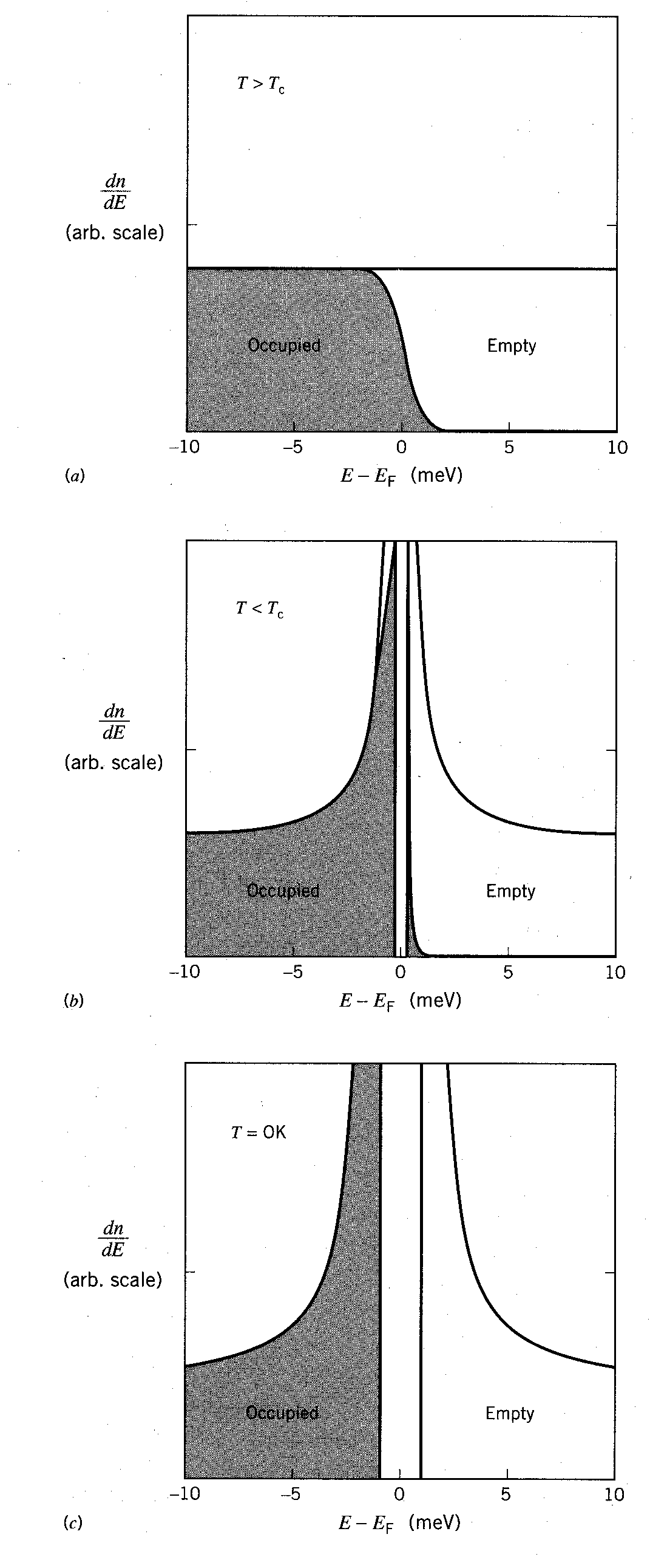 where there are no states. This gap is a result of the binding energy due to the formation of Cooper pairs. As the temperature is decreased further, the number of electrons that can cross the gap is significantly reduced, and thus a greater number of Cooper pairs are formed (see figure, above right). This in turn causes the energy gap to become larger (because the electron density increases), and the process continues reinforcing itself. We can use the ill-mentioned Fermi Energy to describe the size of the energy gap at zero kelvin:
Perhaps now is a good time to do what was promised in the introduction. Think of electrons as single people. These people are so repulsive (smelly and unhygienic) that normally they are forbidden by law to live in the same region (have the same quantum numbers, i.e. they are fermions), so they are forced to live in the outskirts of the city. When winter comes and it gets very cold (below Tc � critical temperature) these people can�t afford their electric bills, so they prefer to live together as outcasts (become bosons). Keep in mind that they are still very stinky, so they don�t converse with each other much (weak interaction between Cooper pairs), but at least in this case they save money on their electric bill by reducing the amount of energy they use (the superconducting state becomes the energy-favorably state). These people are now happy being together. But say for instance that the noise and glamour of the nearby city (magnetic field) started pervading their happy household. The occupants of this boson ranch would stave off the temptation to leave their loved ones (Cooper pairs) for some time (flux exclusion). However if the glitz of the city became too intense (Hc-critical magnetic field) and greatly perturbed them (lattice vibrations � responsible for temperature increases), they would leave their family and return to their previous lifestyles (non-superconducting state).
I think it is beneficial to add that there exists what is called a threshold effect. An explanation of this effect is that some electrons cross the energy gap due to thermal excitations. This number is negligible when well below Tc, but becomes pronounced near Tc. This can help explain the temperature band observed in the transition which we will talk about in the analysis section.
Now while the above description may be a little informal, I think it helps in keeping straight what goes on, at least in a conceptual manner. So now you have some idea of the mechanism behind the microscopic theory of superconductivity (a.k.a. B.C.S.) but you don�t know the half of it. This theory is not adequate for describing high-Tc superconductors. The fact is that nobody understands the mechanism behind high-Tc superconductivity. Not all is lost however, some properties are known.
Most high temperature superconductors utilize layers of copper-oxides, in various configurations, which are separated by layers of other atoms that serve as spacers and also charge reservoirs. When temperatures sink below the critical value, the copper-oxide layers provide a path for the current. The critical temperature is sensitive to the layers of the spacer atoms (i.e. the yttrium or barium insulating plane). The superconductor used in this experiment was the 1-2-3 superconductor that carries the more formal name YBa2Cu3O7 which is called 1-2-3 because of the ratio of yttrium to barium to copper. YBCO is a substance that has a regular crystal structure (see figure, right).
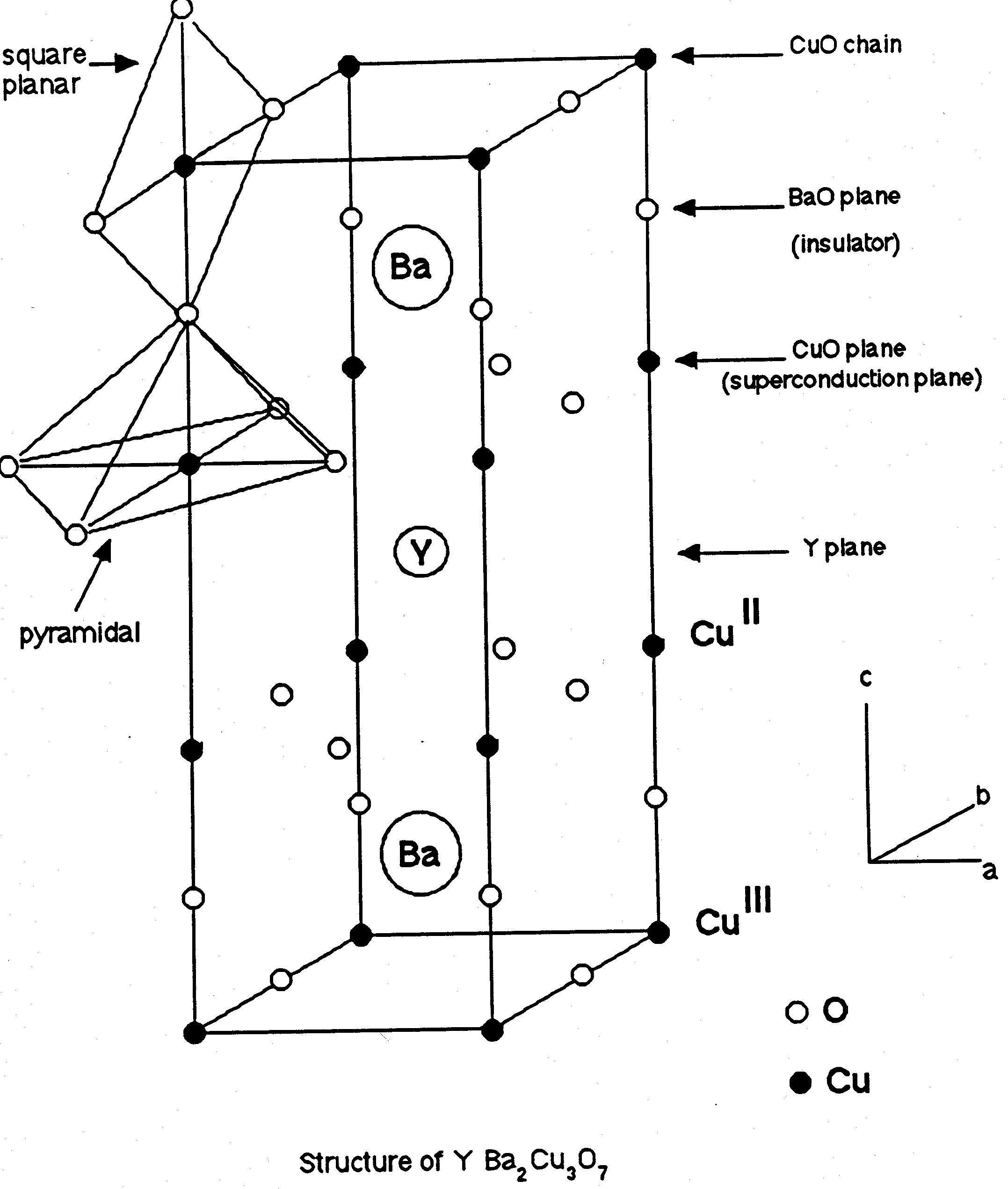
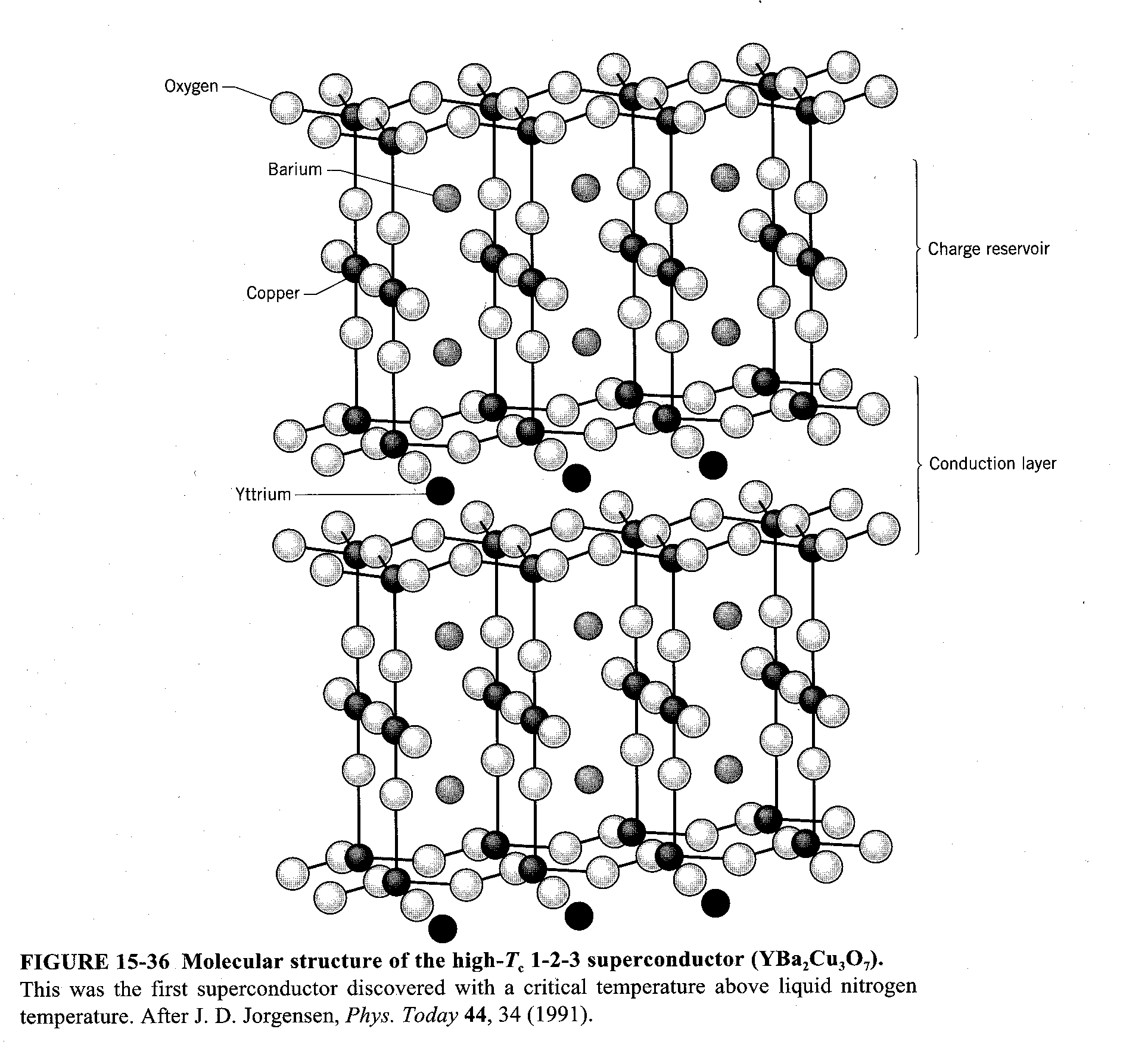 Type II, also called hard, superconductors are composed of ceramics and alloys. All of the superconducting oxides are characterized by large unit cell volumes and a pronounced layer anisotropy. The reason most of the unit cell are large is that the size difference (between the yttrium and barium) generates an internal pressure which is found to increase Tc. Anisotropic (literally means "not turning the same way") is a term used in crystallography to indicate group of crystalline structures in which the optical properties (e.g. refractive index) vary with the direction of the axes (in our picture below the axes are a, b, and c). The axes are defined to be the direction of the vibrations of the crystal. Superconducting properties of these oxides are caused by the availability of plane layers of Cu and O ions in their unit cells. In yttrium crystals in such planes the chains of alternating copper and oxygen ions are clearly distinguished, whereas in most other oxides the plane layers of Cu and O ions are formed by two mutually perpendicular chains of alternating copper and oxygen ions (see figure, above or below right)
 The exact mechanism that leads to high-Tc superconductivity in the copper oxides is, like I previously stated, not known at the present time. I will therefore attempt to explain, in the following order, the structural characteristics of the YBCO superconductors, some trends that characterize the high-Tc superconductors, some current theories of the mechanism of high-Tc superconductivity, and maybe dispel some myths about the influence that certain factors play in the path to superconductivity.
 One structural characteristic of the YBCO (i.e. YBa2Cu3O7-x) that leads to superconductivity is the defective perovskite structure. The top layer of the YBCO unit cell is formed by copper ions that are coordinated to 4 oxygen ions in square planar arrays (see picture above). These copper and oxygen ions in turn form a one-dimensional chain of CuO that runs along the b axis. Moving down parallel to the ab plane, next is a barium and oxygen sheet that acts as an insulating layer. The third layer is formed by copper and oxygen ions. The copper ions in this layer are coordinated with 5 oxygen ions in pyramidal sites (the pyramid structure can be seen drawn in lightly in the sketch). The bases of these pyramidal sites form copper oxygen sheets which are thought to be responsible for superconductivity. An oxygen deficient yttrium layer is next in the sequence and the remainder of the cell consists of another copper oxygen sheet followed by a second barium-oxygen sheet and finally a second set of copper-oxygen one-dimensional chains.
This system has copper cations that are in a mixed oxidation state. This means that some of the copper atoms have a +2 charge, and others have a +3 charge. This leads to an average oxidation of around +2.33. The variable oxidation states serve to preserve charge neutrality in this system. This mixed state was previously thought to be necessary for superconductivity. The basis for those beliefs was that The YBCO sample does not superconduct if the average Oxidation State is +2 (i.e. it was thought that the 2.33 oxidation state was necessary). It was shown however that certain compounds such as La2-xAxCuO4-y (A = Ba, Sr, Ca) do not exhibit superconductivity even if they are in a mixed valence state.
An interesting property of the YBCO superconductors is their stoichiometric flexibility concerning oxygen atoms. The formula that describes the unit cell for these ceramics is formally written as YBa2Cu3O7-x where 0 < x < 1. This is apparently a very well known feature, and it has been shown to have a direct influence on the superconducting properties of these oxides.
In this second section I attempt to give general trends which make Type II superconductors different from Type I. The properties of high-temperature superconductors (i.e. the metal oxides) differ essentially from the properties of ordinary superconductors described by BCS theory. The differences are:
- All new high-Tc superconductors are characterized by a very large anisotropy manifesting itself in their layered structure being perpendicular to the principle crystallographic axis (i.e. the c-axis as seen in earlier picture).
- Large anisotropy becomes evident in the appreciable difference of coherence length for the direction along the principle axis and directions perpendicular to it. The largest anisotropy is found in the bismuth superconductor where the coherence length is ~ 2 Å along one axis, and ~ 40 Å in the transverse direction
- In ordinary superconductors the coherent length is 10-4 cm. In oxide superconductors it is thousands of times smaller. The small value of the coherence points toward a strong coupling of the particles in the pair. Such a coupling results in high critical temperatures.
- The dependence of Tc on the concentration of charge carriers has a non-monotonic character, whereas in ordinary superconductors the temperature Tc rises monotonically with rising concentration.
- Certain measurements of the energy gap in the new superconductors give values that are larger than the energy gaps in the old superconductors.
One model for high-Tc relies exclusively on magnetic fluctuation. Two other theories that are varieties on that theme rely on (i) exchange of spin fluctuations instead of phonons, and (ii) the more radical point of view known as Resonant Valence Bonds (RVB) in which superconductivity is due to condensation of pre-existing singlet pairs in the normal state. Oops! you caught me. I tried to throw in some big buzzwords to impress you. The theories are very difficult and I can only talk sparingly about them. If you must know why I am forced to talk around the theories, I will give you an example of the very base starting point of one of the them. This theory is for the model of superconductivity through electronic polarization, and its starting equation is:
Now would you want to solve the above equation. Me neither.
Let�s return to what we do know. Most of the theories incorporate some sort of magnetic coupling between the electrons, and usually the "one-electron" models do not work because of strong coupling between the electrons.
We at an impasse. I have only talked around, not about, the theories of high-temperature superconductivity, leaving you, the reader, feeling lonely and empty inside. There it is again. Loneliness. How does this theme keep working its way into my paper? I think that is a question of fundamental importance. The whole idea of superconductivity is that these electrons, these normally nomadic, isolated beasts, begin to couple. If we knew why these electrons became aware of their solitude, and sought to remedy it by finding a mate, we would be much closer to answering the question of why superconductors superconduct.
I can�t leave you with nothing. To the best I have found, the watered-down theory of superconductivity is that there exist discrepancies between the high-Tc behavior and what the old theory predicts, but that tells us nothing about the theory of high-Tc superconductors. So maybe I can keep talking around this subject and give you some more distinguishing factors.
If you are still not happy with the hand-waved explanation of high-temperature superconductivity here is my last-ditch summary. It is generally believed that in the types of compounds we used in our experiment, namely the copper-oxides, the electrical conductivity and superconductivity are associated with the copper-oxide planes. This is accepted because changing the composition of the intermediate planes (in our case the yttrium/barium planes) has little affect on the superconducting properties. A large contributor to the fact that much is not known about how these work is because it is not possible to fabricate large single-crystals which have superconducting properties. This forces us to resort to polycrystalline samples in which the single crystallites are very anisotropic (there�s that word again). This anisotropy causes the superconducting properties to be very anisotropic. In particular with the YBCO sample, the coherence length is ~ 0.2 nm parallel to the c-axis (refer to earlier YBCO diagram) while it is ~ 1.5 nm parallel to the ab-planes. There have been experiments done which show that the superconducting current is carried by electron pairs, but as for the mechanism of pairing, no single theory is at hand with which we can tame this most savage of beasts.
Applications (lonely people section):
It is difficult to think of the idea that certain materials conduct electricity with no losses, without immediately thinking of applications. Everything uses electricity to for one reason or another. The notion that you can transmit electricity without losing any to the resistance of the transporting medium is phenomenal. It almost sounds like something straight out of a science-fiction novel.
One of the biggest problems facing the development of high Tc superconductors is finding a direction to search. Most high Tc superconductors are oxides that include copper in the lattice. Is it necessary to include copper in future high Tc materials? This is a puzzling question that is not easily solvable because the theory of high-Tc superconductivity has not been firmly established. This is not a problem facing the development of applications for the already existing high-Tc superconductors. In this pseudo-appendix I will attempt to list and explain some of the most interesting applications, and in keeping with the theme of the paper, how these applications affect lonely people. This is not meant to be a complete list, but only a sampling.
One application is in the field of magnetometry. Superconducting quantum interference devices (SQUIDs) provide the best sensitivity of any technique for magnetic field detection at low frequencies over small areas. SQUIDs have many uses in medical and Navy applications, as well as other potential uses.
Medical uses for SQUIDs:
$100 billion dollars is spent annually on health care for neurological disorders. Existing tools for non-invasive analysis of the human body include magnetic resonance imaging and computer-aided x-ray tomography both of which give structural but not functional information Positron emission tomogaphy (PET) gives information about metabolic activity, but the time response is on the order of minutes. SQUID magnetommetry is in itself both entirely non-invasive, and renders a real-time analysis of electrical activity in the body. Currently these devices utilize liquid helium temperature superconductors because it does not pose an immediate problem to the development of these devices. The way in which high-Tc superconductors (HTSC) will prove valuable in these devices will most likely be in their use as pickup coils. These coils are used to transfer magnetic signals from patient�s heads to the low-temperature superconductors (LTSC) SQUIDs. The benefit of the HTSC coils is in their ability to be placed much closer to the scalp than helium-cooled coils. Lonely people wouldn�t be as lonely if their loved ones with degenerative neurological disorders stuck around for many more exciting years.
Another very important use for HTSC SQUIDs would be in fetal heart rate monitoring. Current techniques use ultrasonic reflections to pick up any heart movement. This isn�t necessarily the most accurate measurement, and perinatologists would prefer to monitor the distinctive electromagnetic heart pulse. This proves difficult in practice however because of the interference from the mother�s heartbeat. HTSC SQUIDs however would provide enough sensitivity to allow for direct monitoring. What better way to make lonely people not-so-lonely, help them make someone to be around them by aiding in their childbearing.
High-Tc superconductors also have widespread applications in the military use. The Navy, our proud seamen, uses HTSC SQUIDs in detection of mines and submarines. It is feasible to use HTSC SQUIDs for this purpose because the background noise levels at the ocean surface are within the range of HTSC SQUID systems. Nitrogen cooling would prove very beneficial on Navy ships because it is presently readily available. It is not clear exactly how this would affect your average lonely guy, but I�m sure you can use your imagination and think of something.
Using SQUIDs could also revolutionize magnetic antennas for extremely low frequency (ELF) communications. Current submarine antennas rely on a long towed cable as an E-field antenna. The antenna is uniaxial and limits the directional range the submarine can travel while maintaining communications. In the late seventies a LTSC SQUID triaxial H-field antenna was demonstrated to be a great improvement, but the research was terminated on the grounds that liquid helium containment was too difficult to in a real operating environment. HTSC SQUIDs could potentially solve this problem since the cooling agent is already in use aboard submarines. The application for lonely people is particularly obvious for this one. Imagine the scene: you are on covert nuclear submarine, destination unknown. Suddenly your heart pangs for your beloved wife/girlfriend/significant other/psychic friend. Without the extremely low frequency high temperature superconducting communications system that is safely at your fingertips, you would have to wallow in the sanctity of your naval crewmates.
Well, another rather important application that was never realized was the superconducting super collider (SSC). This particle accelerator would have used superconducting magnet to accelerate beams of protons to more than 99.9% of the speed of light. But we won�t talk about that.
Maglev trains are also possible with high-Tc superconductors. These trains use superconducting rails to actually levitate the train. Preliminary tests in Japan have proved that this sort of endeavor is possible, and will probably be implemented in the coming years. Picture if you will, lonely passengers riding on one of these trains. The train would metaphorically support the weight of their problems. You could then convince them that their problems were nothing because it would appear as though nothing were supporting them (you can not see a magnetic field after all you know). What a happy world it would be.
HTSC transition-edge bolometers will also most likely appear in applications in the coming years. These devices will have applications in space astronomy and perhaps also in laboratory instruments. This is perhaps the most exquisite example that applies directly to every person on the face of the earth. Who of us hasn�t looked up at the stars and felt alone in this vast stretch of plasma we call our universe. If these devices aid in space astronomy and lead to the discovery that we are not alone in this plight, that maybe there is other life out there, then I think everyone will rest a little easier in knowing that we are truly not alone.
So there are plenty of other applications that I have omitted either because they didn�t apply to lonely people, or because they were so complex that only a few people understand exactly what they are. I will give a list of these applications mainly to have somewhat of a more complete list, and secondarily for the shear purpose of adding big buzz words that make every paper that much more intriguing and bloated. So with no further introduction:
List of other applications for high-temperature superconductors
- Superconductivity based computer systems, to provide tremendous levels of
- Gyrotrons for precision guidance applications
- Traveling wave tubes for electronic applications
- Free electron lasers for research and for military weapon applications
- Superconductive motors for a variety of application requiring reduced power drain
- Energy storage devices
- Fusion applications for potential use in fusion power generation
- Electromagnetic quench guns and launchers using superconductive magnets and zero resistance windings.
- Optical and infrared detectors, novel light modulators
- Hybrid computer logic, crossbar switches, connectors, and interconnects to provide for a ten-times increase in speed and a ten-times size reduction
- Etc
This experiment uses The Superconductor Probe Setup, Amplifier circuit, Diode thermometer circuit board, constant current/voltage power supply, multimeters, data plotter, various coaxial cables, a vacuum pump, liquid nitrogen, a dewar (contains liquid N2 and probe), and helium.
The superconductor probe setup consists of several components. One of these is the container that houses the superconductor during the experiment. This is a cylinder that slides over the end of the actual probe. It is secured to the probe by means of several screws, and sealed using a composite metal that is pressed into the place of connection of the cylinder and probe. The probe is a long (3-4 ft) cylinder about whose center run several wires that lead to the superconductor�s attachment pad (and hook up to the superconductor). The wires used to connect and extract the electrical signal from the superconductor run through the center of the probe, and out the top through a military-grade, air-tight connector (costs ~$135 - don�t break it). This connector has six coaxial cables extruding from it. Two of these cables, marked L and M in our setup (see figure right), lead to the
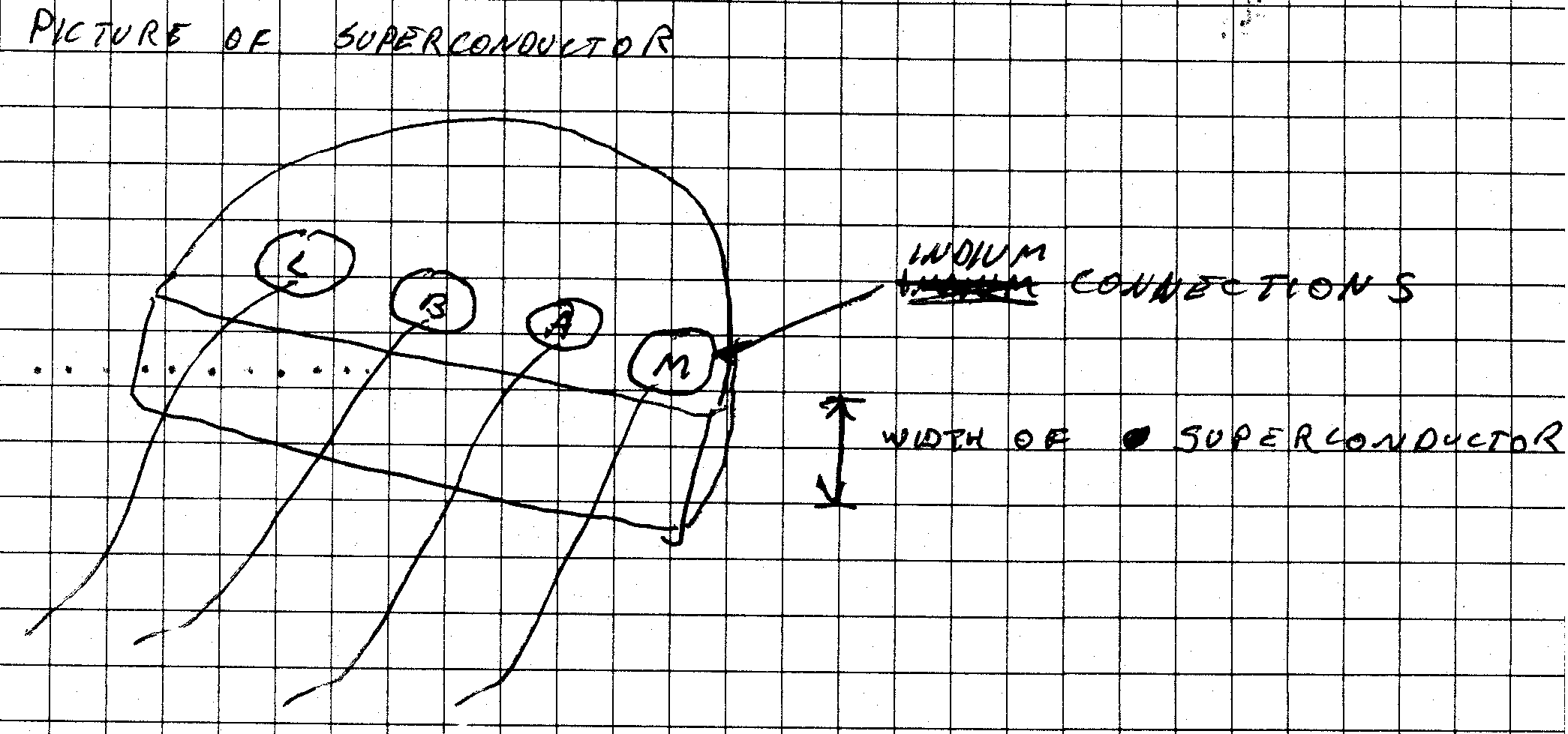 constant current/voltage power supply. Two others, labeled A and B, lead to the amplifier. L and M act to supply a constant, known current through the superconductor, while A and B export the voltage to a high input impedance amplifier. The last two cables lead to the diode thermometer circuit. The diode thermometer signal along with the amplifier signal is sent to the data plotter. This allows a plot of resistance and temperature versus time to be made.
 Procedure:
The next step is to begin the cooling process. Just pour the liquid nitrogen into the dewar and start the data plotter. The transition that occurs while the sample cools is much quicker than the transition while the sample warms. Voila! Then just cut your superconductor into hors d�ouerves size pieces and serve warm. Serves 5-6 and makes a yummy delicious snack.
The temperature at the transition was read directly off of the five separate graphs. There were two temperature values for each graph, one for the temperature at which the sample�s resistance began dropping, and the second from the temperature at which the sample�s resistance once again stabilized. An average temperature, and transition temperature width (i.e. the difference of the upper and lower temp�s) were taken. It is the average temperature that I report as being the transition temperature. The uncertainty of that measurement is the average transition temperature width.
The transition temperature was found to be 97.8 kelvin with an uncertainty of ± 3.75 kelvin. The accepted value for the transition to the superconducting state for YBCO has been quoted in numerous books to be 92 or 93 kelvin. In the spirit of the above raw calculation I will take the accepted value to be 92.5 kelvin. The deviation of the measured value from the accepted is 5.73 %. The uncertainty allows only for a 4.1 % deviation, so the values are not in agreement under the scope of this method. In all likelihood, these values would agree, and their difference arises only from the shortcomings of the experimenters and the apparatus. This will be explained here.
The time the temperature spends in the transition region seems to greatly affect the measured values. The data from the warming up samples has an average transition temperature given by 95.65 kelvin whereas the data from the cooling samples give a much higher average transition temperature of 101.13 kelvin. The warming up data has an average uncertainty of 4.48 kelvin, which is much larger than the cooling data�s uncertainty of 2.65 kelvin.
How are you supposed to make sense of this? The cooling data gives a value that disagrees more with the accepted value, but it is more accurate, and yet the warming gives a "better" value but it lacks faith in the form of certainty. Well I think that there is much more at work here than meets the eye.
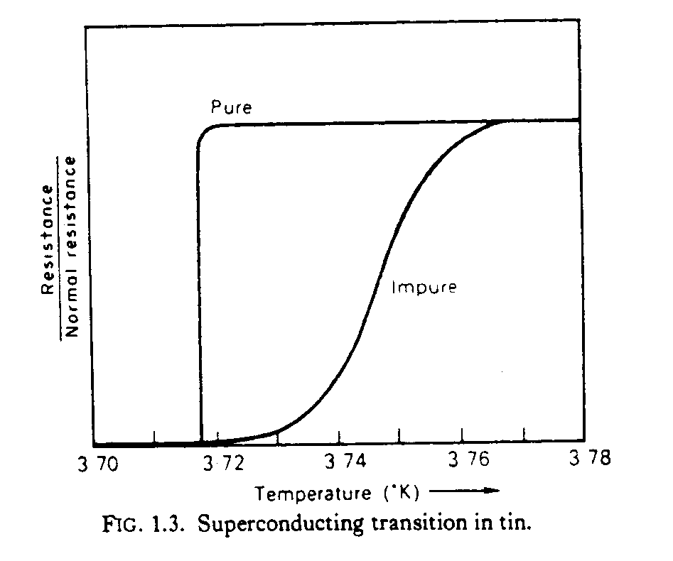 Quite a few things were taken for granted in quoting the numbers I used for my data. It was assumed that the equipment was calibrated correctly every time a data run was made. This is not necessarily a realistic assumption because I am very aware of the stability of the amplifier and diode thermometer that we used, and I would not say with any faith that they would remain calibrated. Let�s just say that if we did stability analysis on the equipment, it would all have negative 2nd derivatives in terms of its potential (concave down-unstable). The fact is that our equipment was not calibrated exactly to room temperature, or liquid nitrogen temperature. On top of that, even if the equipment was calibrated exactly, we found that the diode readout does not increase linearly over the entire range of temperatures.
 More problems. "If the specimen is impure or has a disturbed crystal structure, the transition may be considerably broadened" (see figure on previous page). There is absolutely no way that our YBCO sample was pure. Even if it came from the factory 99.9 % pure, it didn�t stay that way for long. For starters, in the process of assembling the experiment from its shoddy past, the superconducting sample was removed from the confines of its dessicator playground for days at a time. It was constantly being poked at with dirty fingers, metal tools, solder, and direct hot lights. We did make serious efforts while repairing the sample to preserve its integrity, but I�m sure it suffered some damage. I went to Dr. McDevitt�s Chemistry Lab in Welch Hall, where he and colleagues carry out research on superconductivity. I was shown pictures of nearly pure YBCO samples, and pictures of those same samples after being exposed to the air for two days. The result was that the superconductivity was totally destroyed by the formation of crystals that spiked and darted throughout the whole body of the specimen. It wasn�t pretty. Our specimen wasn�t treated so poorly, but I�m sure that its purity could be argued about. That is good for us, we can use that. It was shown in the figure above that the transition becomes smoothed out as the purity of the sample decreases. That is exactly what we saw.
It is impossible to dispute the observed transition. It happened. The disputable question is whether or not that transition was one to a superconducting state. The superconducting state is characterized as a state in which there is no electrical resistance, among other properties. We did not see that. There was a constant resistance offset from zero, however this was probably from noise in the connections and equipment. We must
however remember that the transition to a superconducting state is an abrupt thermodynamic transition. We did see that. Therefore, in all likelihood the observed transition was that to a superconducting state.
The noise was most likely due to the connections and the circuits used to extract a signal. It is not easy to amplify a signal that is nearly zero. It could be argued that the connections (i.e. coaxial cables, etc.) had more resistance than the resistor, and therefore contributed to the total noise. The amplifier was also not very nice. It had a lot of noise associated with it, and only after attaching a capacitor to it could the noise be subdued somewhat. The effect that the capacitor had was not fully understood. I would conjecture that it acted as a filter. Any noise would just contribute to the charge on the capacitor, which would get smoothed out.
Another possible source of error could come from uneven cooling or heating of the YBCO sample. If the temperature changes within the sample were not uniform then internal temperature gradients would be set up. I�m not sure what sort of affect this would have on the results, but it could perhaps lead to things like pressure gradients, which has an effect on the Tc, and could therefore change the results.
It should also be noted that in the absence of an external magnetic field, there is no latent heat associated with the transition. Latent heat is defined as the quantity of heat absorbed or released by a substance undergoing a change of state, as by ice changing to water or water to steam. We can then conclude that since there was no latent heat (i.e. we did not see an increase or decrease in the temperature because of the transition) the transition was not a first-order transition (i.e. solid-liquid, liquid-gas, etc).
Conclusion
Works Cited
Blatt, John M. Theory of Superconductivity, Bantum Press, 1978.Fishbane, Paul M., Physics for Scientists and Engineers. Prentice Hall, 1993.
Hunt, V. Caniel, Superconductivity sourcebook, Princeton, 1988.
Jamisons, J.C., High-Tc Superconductivity: experiment and theory, Dover, 1990.
Rose-Innes, A.C., "Low Temperature Laboratory Techniques", English University Press (1973).
Ullmaier, Hans, Irreversible properties of Type II superconductors, Bantum Press, 1993.
http://web.mit.edu/6.013_book/www/chapter11/11.9.html


 V.
V. 
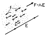
 representing the respective velocities of the carriers relative to that material, the Lorentz force law gives the force on the individual particles.


 u is the unpaired charge density (7.1.6) and J is the current density.
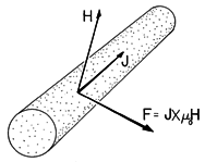
 o H.
o H.  f, then it follows from the Lorentz force law, (1.1.1), that the rate of doing work on individual particles through the agent of the magnetic field is v
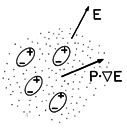
  E on the individual microscopic particles are passed along by interparticle forces to the medium as a whole. A comparison of Fig. 11.9.3 with Fig. 11.9.1 emphasizes this point. For a single species of particle, the force density is the force on a single dipole multiplied by the number of dipoles per unit volume Np. By definition, the polarization density P = Np p, so it follows that the force density due to polarization is
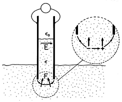

 is a function of position (uniform in the liquid,


 ) =
) = 

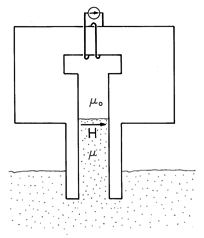


 and i2, the magnetization term in (14) takes a form found for the force on a magnetizable material in Sec. 11.7.] In Example 11.9.2 (where J = 0), we found the force density of (13) to be confined to the fringing field. By contrast, (14) gives no force density in the fringing region (where
  (r). To see this, use a vector identity


 p -
p - 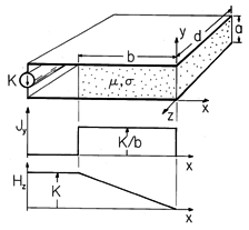


No comments:
Post a Comment